Fire alarm loop wiring explained
How addressable loop wiring works, the difference between Class A (loop) and Class B (radial) configurations, fault tolerance implications, and how loops are managed in practice.
Loop wiring is the defining characteristic of addressable fire alarm systems. Instead of devices wired in radial spurs back to the panel, addressable devices are connected in a ring that starts and ends at the panel. This seemingly simple change in topology has profound implications for fault tolerance — understanding how loops behave under fault conditions is essential for anyone designing, installing, or maintaining an addressable system.
The Difference Between Loop and radial Configurations
In a conventional fire alarm system, detection circuits are typically wired as radials (also called radial circuits) — a cable runs from the panel to the first device, then to the second, continuing to the last device where an end-of-line resistor terminates the circuit. The circuit has one path from panel to end-of-line.
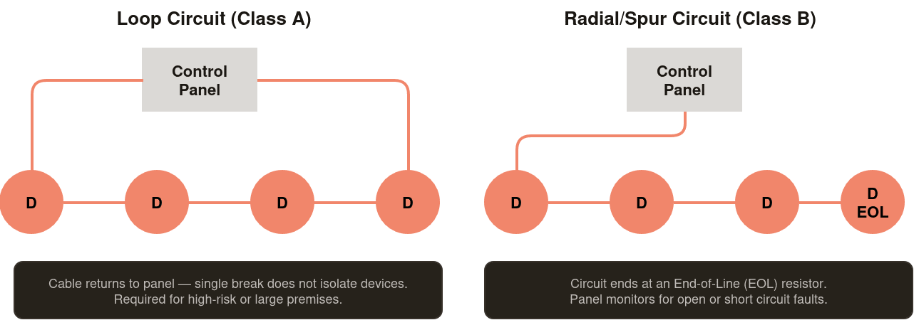
In an addressable system, devices are typically wired in a loop — a cable leaves one port of the panel, passes through each device in sequence, and returns to a second port on the same panel. The circuit has two paths from panel to every device — one from each direction around the ring.
Class A and Class B
Class A and Class B Loop Configurations
The terms Class A and Class B describe how a loop responds to a single wiring fault:
Class A (loop) — the cable leaves the panel, passes through all devices, and returns to the panel. A single open circuit (cable break) anywhere in the loop is tolerated — the panel detects the break and reports a fault, but all devices remain operational because each device can still be reached via the intact half of the loop. The loop has effectively become two radial circuits, each driven from the panel. Detection and alarm functions continue normally despite the fault.
Class B (radial) — the cable leaves the panel and terminates at an end-of-line device. A single open circuit anywhere on the radial isolates all devices beyond the break point. The affected devices cannot communicate with the panel and cannot raise an alarm. The panel reports a zone fault covering all the isolated devices.
| Characteristic | Class A (loop) | Class B (radial) |
|---|---|---|
| Wiring topology | Ring — leaves panel and returns to panel | Radial — leaves panel, terminates at end-of-line |
| Single open circuit fault | All devices remain operational — panel shows fault indication | Devices beyond break are isolated — zone fault, no detection in affected area |
| Single short circuit fault | With isolation modules, devices beyond the short are isolated but rest of loop remains operational | Short circuit disables entire circuit |
| Cable used | Two cables from panel — outgoing and return | One cable from panel |
| BS 5839-1 recommendation | Recommended for most applications | Acceptable in lower-risk applications |
Short circuit isolation
Short Circuit Isolators
A loop provides excellent tolerance to open circuit faults but is more vulnerable to short circuits. A short circuit anywhere on the loop — if unmanaged — will disable the entire loop because neither half of the ring can communicate past the short.
The solution is short circuit isolators (SCIs) — devices fitted at intervals around the loop that automatically isolate a short circuit fault to the segment between two adjacent isolators. When a short is detected, the isolators on either side of the short operate, disconnecting the faulty segment while leaving the rest of the loop operational. The panel reports a fault for the devices in the isolated segment, but all other devices continue to function.
BS 5839-1 recommends that isolators are fitted at regular intervals around the loop — typically so that no more than 32 devices are at risk of isolation by a single short circuit. In buildings where continuous operation is critical, isolators at every device (built into the device base) provide maximum protection.
Loop capacity and loading
Loop Capacity and Loading
Every panel loop has a maximum capacity — both in terms of the number of devices it can support and the total current it can supply. The designer must verify that the total device count and total current draw of all devices on the loop does not exceed the panel’s loop capacity specification.
Current loading is particularly important because addressable devices draw current continuously from the loop — even in quiescent (normal) condition. A loop loaded close to its current limit may exhibit communication errors or spurious faults under certain conditions. The current draw of each device type is specified by the manufacturer and must be summed for all devices on the loop during design.
Common questions
Frequently Asked Questions
Yes — adding devices to an existing loop is one of the most common system modifications. The engineer must confirm that the loop has sufficient remaining capacity (device count and current budget), assign a unique address to each new device without conflicting with existing addresses, programme the new devices into the panel database with their location descriptions and cause and effect relationships, and update the as-installed documentation. Adding devices to a loop without updating the panel programming and documentation is a common source of problems — devices that appear on the panel with no description, or devices that are not included in the cause and effect programme, provide no reliable protection.
The maximum loop length depends on the panel manufacturer’s specification and the cable resistance per metre. As cable resistance increases with length, the voltage available at the furthest device on the loop decreases — and the communication signal becomes weaker. Most manufacturers specify maximum loop resistance rather than maximum length, typically in the range of 40–80 ohms total loop resistance. The engineer calculates the maximum cable length by dividing the permitted resistance by the resistance per metre of the cable type used. Using lower-resistance cable allows longer loops.